
What is C.A.N Bus?
Controller Area Network (CAN) Bus is a standard communication protocol designed for micro-controller or some devices to communicate with each other without a host computer for vehicles.
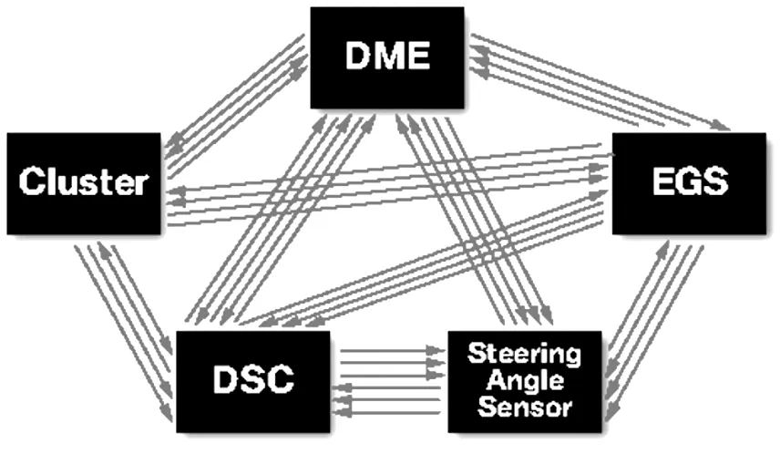
To understand what CAN BUS is, it's good to liken it to our body. Think each part of a car as human’s parts. They are all connected via CAN Bus network, as it was described as pictures below.
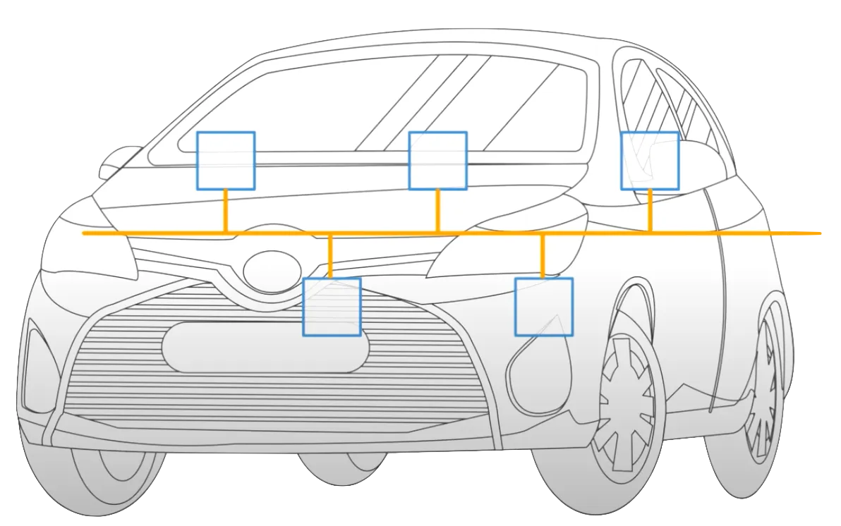
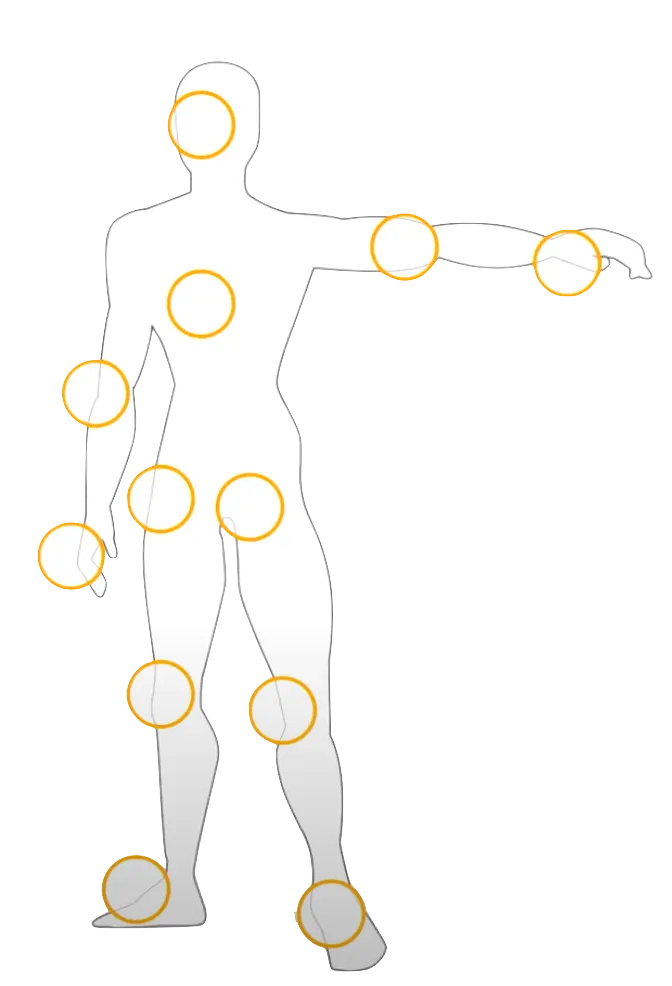
In automotive CAN bus systems, ECUs can be like engine control unit, airbags, audio systems, cooling systems, ..etc. Modern cars have up to 70~80 ECUs, and they all have some informations that have to shared with other parts of the network.

The ‘nodes’ are also called ECUs(Electronic Control Units)
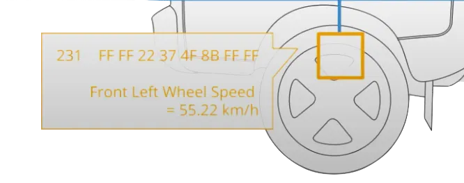
An ECU can prepare informations (such as speed sensor) and broadcast this via the CAN bus. This information should be shared with other ECUs, so it will broadcast this via the CAN bus.
CAN bus connection / physical & data link layer
The physical communication happens via the CAN bus wiring harness, consisting of two wires, CAN low and CAN high. The broadcasting data is accepted by all other ECUs on the CAN Network - and each ECU can then check the data and decie whether to receive or not.

In physical terms, CAN network is described by data link layer & physical layer. CAN(Network) corresponds to the 1/2 Layer in the OSI 7-layer model.
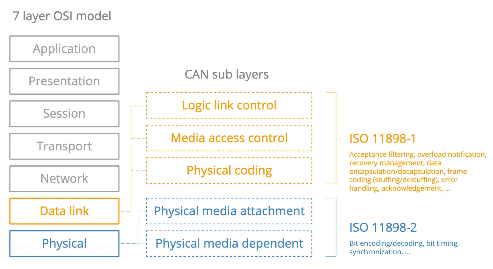
In case of high speed CAN, data link layer is described by ISO-11898-1, and physical layer is described by ISO-11898-2.
CAN bus physical layer defines things like cable types, electrical signal levels, node requirements, cable impedance etc.
For example, ISO-11898-2 dictates:
•
Baud rate
CAN nodes must be connected via a two wire bus with baud rates up to 1Mbit/s (Classical CAN) or 5Mbit/s (CAN FD)
•
Cable length
Maximal Can cable lengths should be between 500m (125kbit/s) and 40m(1Mbit/s)
•
Termination
The CAN bus must be properly terminated using a 120Ohms CAN bus termination resistor at each end of BUS
Why CAN bus?
Simple & low cost
ECUs communicate via a single CAN system instead of via direct complex analogue signal lines - reducing errors, weight, wiring and costs
Easy access
The CAN bus provides 'one point-of-entry' to communicate with all network ECUs - enabling central diagnostics, data logging and configuration
Extremely robust
The system is robust towards electric disturbances and electromagnetic interference - ideal for safety critical applications (e.g. vehicles)
Efficient
CAN frames are prioritized by ID so that top priority data gets immediate bus access, without causing interruption of other frames or CAN errors
History of CAN bus
Pre CAN
Car ECUs relied on complex p2p wiring.
Before CAN bus system exists, each nodes were connected with all other parts by lines. This was very uneffiecient ‘cause the number of ECUs continue to increase when time passes.
Short history
•
1986
Bosch developed the CAN protocal as a solution
•
1991
Bosch published CAN 2.0 (CAN 2.0A: 11bit, 2.0B: 29bit)
•
2003
ISO 11898 becomes a standard series
•
2012
Bosch released the CAN FD 1.0 (flexible data rate)
•
2015
The CAN FD protocol is standardized (ISO 11898-1)
•
2016
THe physical CAN layer for data-rates up to 5 Mbit/s standardized in ISO 11898-2
From now on?
Today, CAN is standard not just in cars, also most automotives(trucks, buses, tractors), ships, planes, EV batteries, machinery, …etc.
Cloud computing, IOT and autonomous drivings are main keywords of this day. But if the CAN bus turned into online, there will be plenty of security issues.
Also, traditional vehicles are getting expands and so classic CAN is getting much more loads. To fix this, CAN FD has been designed as next-generation CAN bus.
Specially, CAN FD offers 3 benefits.
•
Data rates up to 8 Mbit/s
•
Data payloads of up to 64 bytes
•
Improve security via authentication
CAN frame?
There are some forms to keep to communicate over CAN.
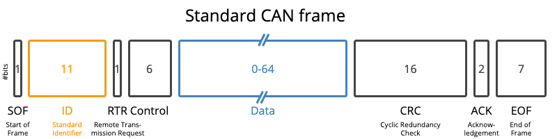
Below is a standard CAN frame with 11 bits identifier (CAN 2.0A), which is the type used in most cars. The extended 29-bit identifier frame (CAN 2.0B) is identical except the longer ID. It is e.g. used in the J1939 protocol for heavy-duty vehicles. Note CAN ID and Data are highlighted - these are important when recording CAN bus data.
•
SOF (Start of Frame) : 1
SOF is a ‘dominant 0’ to tell the other nodes that a CAN node intends to talk.
•
ID (Standard Identifier) : 11
ID is the frame identifier - lower values have higher priority
•
RTR (Remote Transmission Request) : 1
RTR indicates whether a node sends data or requests dedicated data from another node
•
Control : 6
Control contains the Identifier Extension Bit (IDE bit) which is a ‘dominant 0’ for 11-bit. It also contains the 4-bit Data Length Code (DLC) that specifies the length of the data bytes to be transmitted (0 to 8 bytes)
•
Data : 0~64
Data contains the data bytes aka payload, which includes CAN signals that can be extracted and decoded for information
•
CRC (Cyclic Redundancy Check) : 16
CRC is used to ensure data integrity
•
ACK (Acknoledgement) : 2
ACK slots indicates if the node has acknowledged and received the data correctly
•
EOF (End of Frame) : 7
EOF marks the end of the CAN frame
Example of CAN Frame
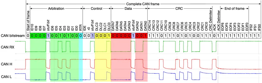
As you can see in the picture, the first bit is SOF. After that, there are 11 green bits. But there is a ‘stuff bit’ in the middle of Arbitration(ID). I will attatch explanation of this below.
What is stuff bit?
After ID, 1 RTR(skyblue) bit, and 6 Control bits (also stuff bit). You can also see 8 Data bits. The data bits’s length is flexible. There are 16 CRC, 2 ACK, and 7 EOF bits.
CAN Bus error
The CAN frame has to satisfy a number of properties to be valid. If an erroneous CAN frame is transmitted, CAN nodes will automatically detect this and take action accordingly. This is referred to as CAN bus error handling, in which CAN nodes keep track of their own 'CAN error counters' and change state (active, passive, bus off) depending on their counters. The ability of problematic CAN nodes to transmit data is thus gracefully reduced to avoid further CAN errors and bus jamming.
You can see it at the csselectronnics’ bus error intro.


